
How We Custom-Designed a Compact Copper Granulator for a Space-Limited Yard
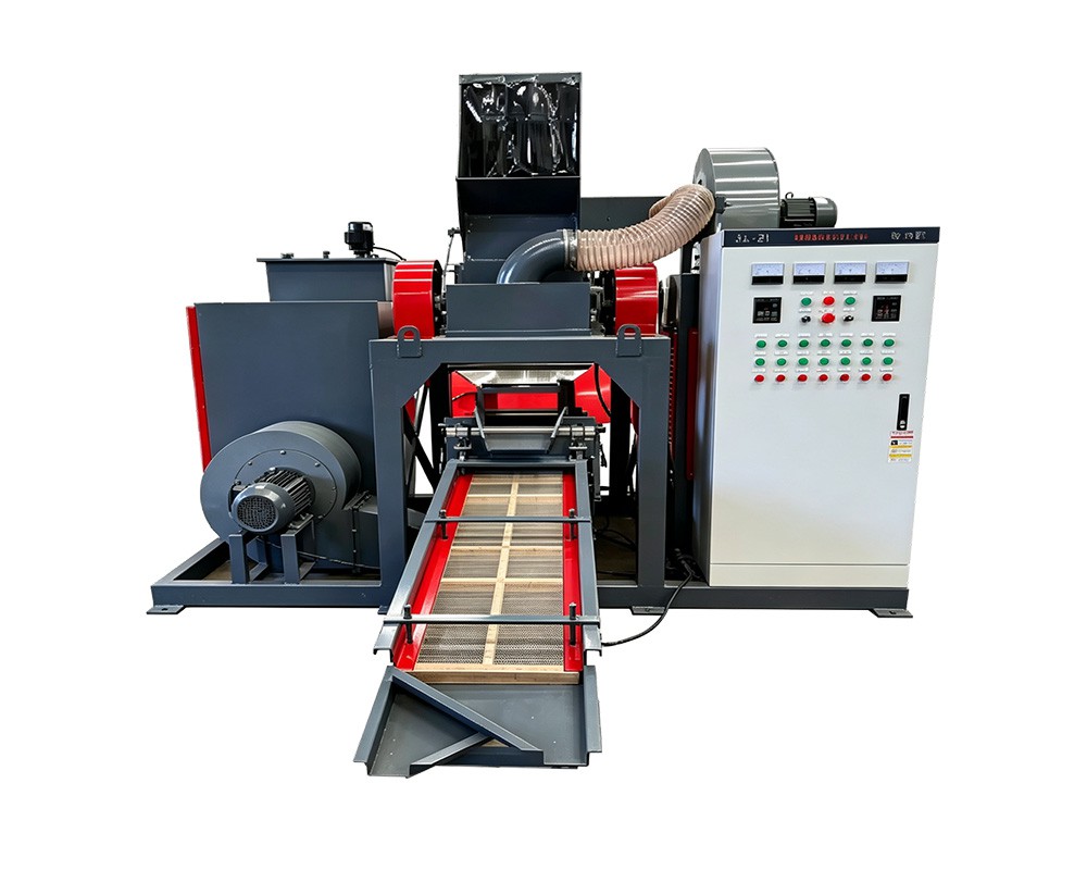
How We Custom-Designed a Compact Copper Granulator for a Space-Limited Yard
Published in News & Insights · Company News
By Henan Jiacui Intelligent Equipment Co., Ltd.
The most common constraint in cable recycling is not capital and it is not copper price. It is floor space. Urban yards, leased units and sites shared with other operations frequently have less usable area than the equipment footprint described in a brochure — and a machine that does not physically fit cannot be made to fit by negotiation.
This article describes a recent configuration project for a customer whose available bay was narrower than our standard layout. It explains what we changed, what we deliberately did not change, and what ‘custom-designed’ honestly means in practice.
The constraint
The customer operates a scrap yard on a leased site with an existing building. The bay allocated to cable processing was approximately 7 m long by 3.2 m wide, with a 2.6 m clear height to a steel beam at one end and a single vehicle access point. Power was available at 60 kW, three-phase.
On paper, a mid-size line would fit the throughput requirement of roughly 300–400 kg/h. In practice the standard arrangement — feed conveyor, granulator, gravity separator, screen, dust unit laid out in a straight line — needs closer to 11 m of run plus clearance for service access on both sides. Laid out in that bay, there would have been no room to withdraw a screen or open the chamber.
This is a common situation. The footprint figure in a specification is the machine’s envelope, not the working envelope. Service access, material staging and discharge clearance typically add 40–60% to the area required.
The four changes we made
1. The line was arranged in an L, not a straight run
The granulator sits at the corner, fed from a short inclined conveyor along the long wall, with the separation section turning through 90 degrees along the short wall. This uses the bay’s length in one direction and its width in the other, instead of demanding a single continuous run that the building could not provide.
2. The gravity separator was repositioned above the screen
Stacking the separator and screen rather than placing them in series recovered roughly 2.5 m of floor. The trade-off is that the screen is reached by a fixed access platform rather than directly from floor level, so the platform was designed with handrails and a defined load rating rather than improvised.
3. Dust collection was split into two smaller units
A single central dust collector would have needed a duct run across the bay and a filter unit in the one place with vehicle access. Two smaller units — one at the granulator, one at the separator/screen — cost slightly more but avoided both the ducting and the loss of the access point. Capture performance was verified at commissioning, not assumed.
4. All service access was consolidated onto one side
Blade changes, screen withdrawal and separator adjustment were all moved to the aisle side. This is the change that matters most in a narrow bay: if a screen can only be withdrawn into a wall, the machine is effectively unmaintainable regardless of how well it runs on day one.
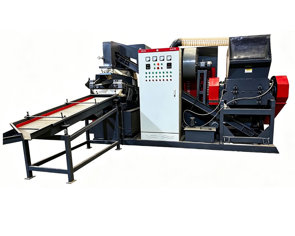
An L-shaped arrangement was used to fit a 7 m by 3.2 m bay.
What we did not change
Compromise in a tight space should be confined to geometry. These items were treated as fixed:
Item | Why it could not be compromised |
|---|---|
Blade access | A blade change that requires dismantling guarding will not be done on schedule, and blade condition drives purity. Access had to remain practical. |
Blade-to-screen gap | The gap determines granulate size and therefore separation performance. It was set to specification and measured at four positions, exactly as on a standard unit. |
Separation stages | The customer still received air separation plus vibrating-screen classification. Floor space is not a reason to remove a stage that determines yield. |
Dust capture | Two smaller units, but the same capture standard at every generation point. Dust is an occupational and permitting issue, not an aesthetic one. |
Guarding and interlocks | Re-arranging a line must not create a reach-in hazard. All interlocks were re-verified after reassembly. |
Electrical protection | The supply was 60 kW available; the installed load was matched to it with proper protection, not by removing safety devices. |
The resulting layout
Zone | Approximate area used | Note |
|---|---|---|
Feed staging and inclined conveyor | 1.2 m × 3.0 m | Short conveyor, loaded from the vehicle access point |
Granulator and drive | 1.8 m × 2.2 m | At the corner of the L, chamber opening to the aisle |
Separator and screen (stacked) | 1.6 m × 2.0 m | Platform access, handrailed |
Dust collection (two units) | 1.0 m × 1.6 m total | One at the granulator, one at the separator |
Discharge and product staging | 1.4 m × 2.0 m | Big-bag stations for copper and plastic |
Service aisle | 0.9 m clear | Continuous along the access side |
Total footprint used was approximately 7.0 m × 3.1 m — inside the bay, with a continuous service aisle and without encroaching on the vehicle access point.
Performance after commissioning
The unit was commissioned on the customer’s material over two days, with throughput and sampling checks on the second day. It met the throughput requirement for their mix, and the copper product met the specification agreed with their buyer. Two things needed attention in the first month, both routine:
- The stacked separator needed its deck angle re-set once the machine had settled on its mounts. This is normal on a new installation and is why we ask customers to re-check angle and belt tracking after the first 100 operating hours.
- The screen inspection interval was shortened for the customer’s material mix, which included taped harness off-cuts. A five-minute inspection every 90 minutes of continuous running kept throughput stable.
What ‘custom-designed’ does and does not mean
This is worth stating plainly, because the phrase is overused in equipment marketing.
What we did was a configuration and layout engineering project. We changed the arrangement, the access strategy, the dust system architecture and the discharge positions. We did not design a new granulator rotor, a new separation principle or a new blade geometry — and any supplier who claims to do that for a single yard-sized order is either overstating the work or charging for development that will not be supported in ten years’ time.
The practical test of a genuine custom configuration is simple: ask for the layout drawing before you order, with service clearances marked. If the supplier cannot produce one, the ‘custom’ claim is a sales word rather than an engineering one.
Frequently Asked Questions
Can you fit a granulator into a very small space?
Often, within limits. The constraints that cannot be engineered away are the machine envelope itself, the need to withdraw a screen, and the need to open the chamber for blade changes. Everything else — line arrangement, stacking, dust system architecture, discharge position — can usually be adapted. Send us the bay dimensions, clear height, access width and available power, and we will tell you what fits and what does not.
Does a compact layout reduce capacity or purity?
It should not, if the separation stages and the blade-to-screen gap are preserved. Where capacity is lost, it is usually because a longer feed conveyor or a larger separator was removed to save space — those are design compromises, not inevitable consequences of a small footprint.
How much space do I need beyond the machine footprint?
Plan for roughly 40–60% additional area for service access, material staging and discharge clearance. A machine specified at 2 m × 3 m typically needs a working envelope closer to 3 m × 4.5 m once those are included.
Can the layout be changed after installation?
Sometimes, but it is far cheaper to decide before fabrication. Moving a separator or a dust unit later means new ducting, new electrical runs and a re-commissioning exercise. This is why we ask for bay dimensions and a photograph of the space at the quotation stage.
Request a Layout Drawing
If your available space is the reason a standard layout will not work, send us the bay dimensions, clear height, access width and a photograph. We will produce a layout drawing with service clearances marked before you commit to anything — and tell you honestly if the space is too tight for the throughput you need.
Send us your material description, daily tonnage and target output, and our engineering team will respond with a model recommendation, a capacity calculation and a quotation. You are also welcome to book a live video walk-through of the Henan Jiacui Intelligent Equipment Co., Ltd. factory in Zhengzhou, Henan, China, or request a reference list of installations running comparable cable or waste streams.
About the Author and the Manufacturer
This article was prepared by the technical sales and engineering team of Henan Jiacui Intelligent Equipment Co., Ltd. (brand name JIACUI). Founded in 2015 in Zhengzhou, Henan Province, China, JIACUI designs and manufactures solid waste recycling equipment and copper wire granulation systems in a 5,000 m² factory with more than 100 employees. Our equipment holds CE, ISO and CSA certification, uses ABB and Siemens control components built to European design standards, and has been delivered to more than 400 customers in over 100 countries. Factory audits have been completed with SGS, BV and TÜV. We hold 27 patents covering shredding, granulation and separation technology. Where this article quotes performance figures, those figures come from our published model specifications and from commissioning tests on real installations; actual results depend on cable composition, feed preparation and operating practice.
Previous: Factory Test Video: Running 500kg/h Cable Granulation Line for European Client
Next: None